GUIDE
From a STEP or STL file to a DXF cutting pattern
The workflow from a CAD surface to a ply on the cutting table, using DrapeCut. Ten minutes for a first part, most of it deciding where the cloth goes on first.
1. Export the surface
Export the mould face or the part's outer surface, not the whole solid. Units should be millimetres. Two formats work:
- STEP keeps the CAD faces, and DrapeCut lets you pick which of them the ply should cover. Use it when the part has a flange, a return or a trim edge that a different ply will handle. Meshing takes a few seconds on the server.
- STL is a mesh. Export it fine: a chord tolerance of 0.1 mm or better on a part of a few hundred millimetres. A coarse STL gives a faceted surface and a jagged shear map. The limit is 250,000 triangles and 40 MB.
2. Upload it
Drop the file on the part area at drapecut.com or choose it. Nothing is written to disk unless you are signed in. For a STEP, click the faces to cover and confirm. The tool then asks whether the model is a mould or the part, and for a part whether it is seen from its tool side or its bag side, a whole laminate away from the tool. Which way the cloth goes follows from where you click the seed: on a mould it lies on the side you click from, on a part it lies the other way, into the part. Answer the question carefully. A pattern developed on the wrong side of the part is out by the laminate thickness, which on a channel is several millimetres of width, and no ply thickness setting will put that right.
3. Seed the net
Click where the first fibre crossing will sit on the mould. This matters more than any other setting: a pin-jointed net grows outward from the seed, so the seed is the place the cloth is laid first and smoothed away from. Deep in the part beats near an edge, because the two axes of the net run from the seed and the ply only reaches as far as they do. The seed snaps to the part's corners, the middle of each edge and its centre; the dot under the pointer lights up before you click. A part from a STEP file uses the CAD's own corners. Suggest seed tries a handful of candidates and picks the one that covers most. Drag to orbit, click to re-seed; the selected ply re-solves each time. One seed serves every ply of the laminate.
4. Set the warp direction
The warp slider sits in the selected ply's row under Laminate and turns the net about the surface normal at the seed. 0° and 90° give the same net on a symmetric part; 45° is what a ±45° ply looks like. The angle is measured in the tangent plane at the seed, which is where the laminate schedule's fibre angle is defined too.
5. Choose the weave
The weave sets two numbers: the tow pitch, which is the spacing of the net's links, and the locking angle, past which the tows jam. A 2×2 twill 3k is 2 mm pitch and about 45°. Pick from the list or type your own. A finer pitch takes longer to solve and rarely changes the answer; the grid is capped at about 400 × 400 nodes and the pitch is coarsened if you go beyond it. Locking angles by weave.
6. Read the shear map
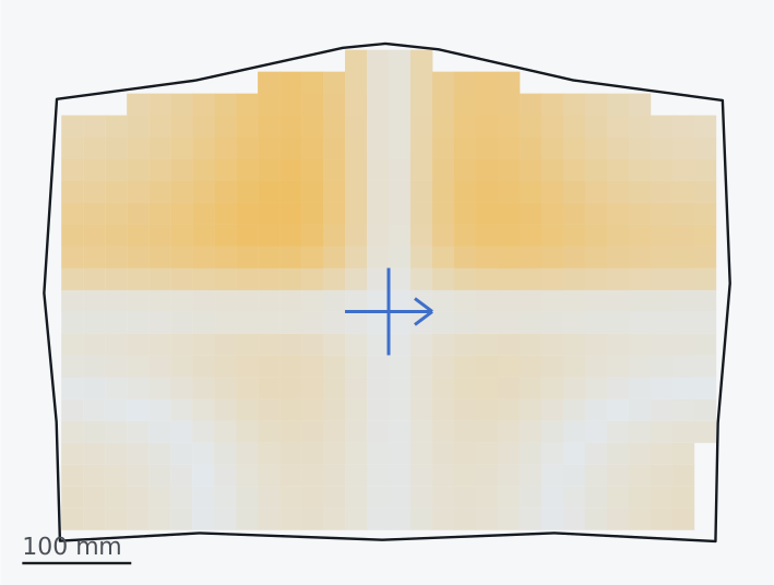
Grey is flat, gold is 45°, dark red is past the locking angle. Selected ply gives the maximum shear, the number of cells past lock, the flat size and how much of the part the ply reached. If the red is somewhere that gets trimmed off, ignore it. If not, move the seed, turn the warp, choose a weave that locks later, or split the ply.
7. Cover with pieces if one will not reach
When the coverage figure is below 100%, or the shear is unacceptable, Cover with pieces lays several pieces of that ply from separate seeds, assigns every part of the surface to the nearest, trims each piece to its own ground plus the overlap set under Pattern, and exports them together or one at a time. Click the part to place another piece by hand. Each piece is a layer group in the DXF.
8. Stack the laminate
The ply list under Laminate is the laminate schedule. Add ply puts another ply on the same seed; type its warp angle in the row, or paste the whole schedule at once as 0, 45, -45, 0. Say whether the model is a mould or the part (the cloth lies on the side of a mould you click the seed from, and the other way into a part) and give the cured ply thickness: each ply is then developed on its own mid-plane, half a ply off the tool for the first and a whole ply further for each one above it, which is what makes the plies of a channel come out different widths. The selected ply drapes as you work; the rest wait for one Drape button, so the slow job is deliberate. Under Pattern, All plies exports the laminate as one DXF or PDF.
9. Download the DXF
The file is R12 DXF, the dialect every plotter, cutting table, laser and CAD package reads. It is in millimetres with the warp along x. Layers:
| Layer | Contents |
|---|---|
| OUTLINE | The cut line, one closed polyline per ply. |
| GRID | Fibre lines every 5th or 10th tow, if asked for. Useful printed on the template so the cloth can be aligned to it. |
| MARKS | The seed cross and warp arrow: where to start laying, and which way the warp goes. |
| LOCK | Cells past the locking angle, so the trouble spots are visible on the template. |
| RELIEF | Dart cuts, when Relieve with darts was used. |
A laminate or a set of pieces exported together prefixes every layer with the ply number, P1_OUTLINE, P2_OUTLINE and so on, with each pattern at its true flat position so the file reads as the layup. For cutting, export plies one at a time.
10. Cut and lay up
Cut on a plotter or a CNC table straight from the DXF, or print at 1:1, tile the sheets, and cut round a paper template with the cloth between release film. The seed mark goes on the mould first. Smooth the cloth out along the two axes, then into the quadrants. That order is what the model assumed, and it is also the order that gives the least bunching.