GUIDE
Pin-jointed net draping: the kinematic model
The model behind DrapeCut and behind most draping tools in composites CAD. It is a geometric construction, not a mechanical simulation, and its usefulness comes from knowing exactly which of those it is.
The idea
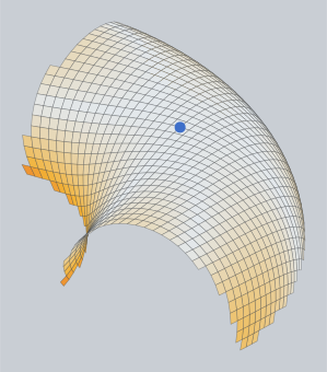
Represent the cloth as a net of rigid links, one tow pitch long, joined by frictionless pins at the crossings. The links cannot stretch and the pins let the crossing angle change freely. Lay the net over the surface from a starting point, and every node's position is fixed by geometry alone: it must be one pitch from each of its two already-placed neighbours, and it must be on the surface. The construction goes back to Mack and Taylor's 1956 paper on fitting woven cloth to surfaces of double curvature, and it is what "kinematic draping" means.
How the net is built
- The seed. A point on the surface where the first crossing sits, and a direction in the tangent plane there for the warp. The weft is at 90° to it.
- The axes. From the seed, a geodesic is traced across the surface in the warp direction and another in the weft direction, and nodes are placed along each at one pitch spacing. These four half-axes are the cloth's straight tows through the seed.
- The quadrants. Every other node has two placed neighbours, one along each axis direction. It lies where two spheres of radius one pitch, centred on those neighbours, intersect the surface. Of the two intersections, the one continuing outward is taken. Filling proceeds quadrant by quadrant, away from the seed.
- The boundary. A node that lands off the surface ends its tow. If the surface comes back within a short distance, as it does across a hole, a slot or a notch, the tow bridges the gap and lands again, as real cloth would. Otherwise the ply ends there, and its outline is traced.
- The pattern. Each cell's shear angle is read from its two link directions. The flat pattern is the net's outline mapped back onto the undeformed square grid, which is simply the node indices times the pitch.
What it predicts
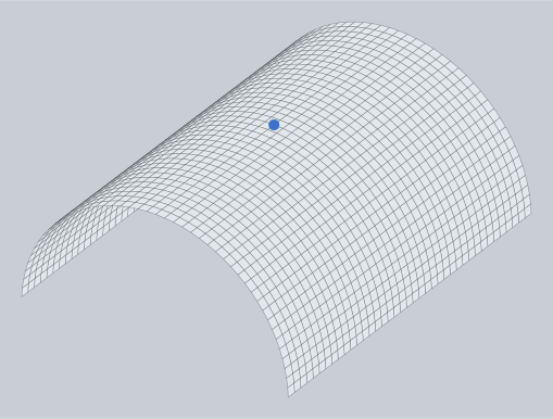
Fibre paths on the part, the shear angle in every cell, the flat cutting pattern, and how much of the part a ply from a given seed can reach. It is deterministic, has no material parameters, and solves in well under a second, so it can be re-run on every click while a seed or a warp angle is chosen.
What it leaves out
- Friction between cloth and tool, and between plies. Real cloth is dragged by the tool as it is smoothed down; the model lets it slide freely.
- Tow bending and shear stiffness. The model shears at no cost right up to the locking angle, then stops reporting. Real cloth resists progressively, and the resistance redistributes the shear a little.
- The laminator. The order in which the cloth is smoothed down, and the tension applied, change the outcome. The model assumes seed first, then the axes, then the quadrants, which is a good order but not the only one.
- Multiple plies interacting, blank holders, diaphragms and the process physics of forming.
The result depends on the seed and the warp direction, and it should: those are the decisions the model exists to inform. Two different seeds give two different, both valid, patterns, for two different ways of laying the same cloth on the same mould.
Kinematic or finite element
For deciding the cut shape and spotting where the cloth will fight, kinematic draping is what most workshops act on, and its answer agrees with forming simulation to within the variation between two laminators. For process design, diaphragm or press forming, predicting wrinkles as a mechanical event, or thermoplastic consolidation, finite-element forming simulation with measured material properties is the right tool. DrapeCut is the first kind, in the browser, free while in beta.